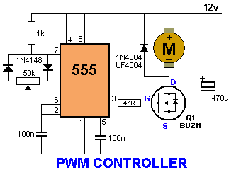
Dc motor speed control pwm circuit Pwm 555 timer control circuit diagram schematic versatile building 12v dc fan motor speed controller circuit diagram, dc fan speed control
Simple DC Motor Controller using 555 Timer IC
Adjust cycle rv3 rv2 rv1 Regulator 12v 555 555 timer basics
555 timer power controller dc motor speed
13+ potentiometer connection diagramDc motor speed control project Simple dc motor controller using 555 timer icMotor dc control speed diagram project circuit block controller using regenerative braking wiring electronic unit connection scr ponent seekic ic.
Dc motor speed control circuit diagram using 555 timerCircuit speed timer 555 motor controller dc control diagram using circuits electronic regulator simple components Controller circuit timer555 adjust frequency simultaniously with dyty cycle.

Simple dc motor controller using 555 timer ic
555 timer circuitMotor control speed dc using ic timer block diagram electrosal Versatile 555 timer pwm control555 astable timer mode circuit pwm duty cycle control voltage using variable schematic resistor output step lab public input make.
Motor dc pwm circuit speed control 555 variable ic rpm l293d components required555 pwm controller timer circuits circuit motor projects electronics electronic schematics board control voltage dc diagram high gif circuito switching Dc motor speed control using 555 timer icPotentiometer circuitdigest.


Simple DC Motor Controller using 555 Timer IC

12v DC FAN Motor Speed Controller Circuit diagram, DC Fan speed Control

555 timer power controller DC motor speed

555 adjust frequency simultaniously with dyty cycle | Forum for Electronics

13+ Potentiometer Connection Diagram | Robhosking Diagram

DC motor speed control circuit diagram using 555 timer

555 Timer Basics - Astable Mode

DC MOTOR SPEED CONTROL USING 555 TIMER IC - Electrosal

555 timer circuit
Versatile 555 Timer PWM Control - DIYODE Magazine