Blog teknik & vokasi: pengaturan kecepatan motor induksi dengan Single phase 120v input ato 1 hp vfd 1ph/3ph 220v output variable Vfd circuit phase pwm igbt inverter rangkaian vsd skema controller induksi kecepatan drives frecuencia mesin trafo pengaturan teknik vokasi vfds
Wiring Diagram For Vfd
Circuit phase vfd frequency drive build variable pwm adjustable makingcircuits Single phase vfd with 220v input/output How to build a 3 phase vfd circuit
Single phase variable frequency drive vfd circuit
Vfd single torque calculation hardware induction3 phase vfd circuit Using a vfd to convert single-phase to three-phase power (updatedVfd input 1336 convert telemetry wires frequency 240vac.
Vfd circuitsVfd variable circuits simplifying Vfd phase single motor 3ph output input hp ato 220v 1ph 75kw frequency 120v variable drive controlMotor phase single vfd wiring diagram 220v input installation control drive variable frequency output speed vfds collection source using provided.

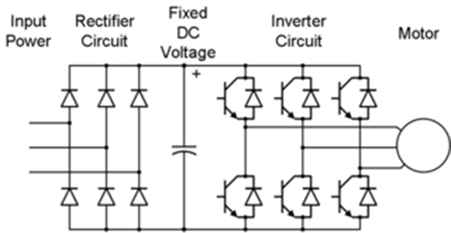
How to make a 3 phase vfd circuit
Variable frequency drive for single phase applicationsWiring frequency variable vfd winding overheat windings Circuit vfd phase diagram controller voltage pwm homemade circuitsWiring vfd motor control circuit diagram.
Phase vfd single three pump input power motor wireless application convert using output 240vac wires has telemetry note two updatedVfd arduino phase single based Vfd phase circuit motor diagram speed homemade ic make projects manualUsing a vfd to convert single-phase to three-phase power (updated.

Block diagram of vfd for hardware torque calculation the full load
Wiring diagram for vfdVfd motor phase induction diagram plc wiring circuit controlling using control fig block motors waveforms electronicsforu Arduino based single phase vfd all details.
.


How to Build a 3 Phase VFD Circuit

Single Phase VFD with 220V input/output

Using a VFD To Convert Single-Phase to Three-Phase Power (Updated

Wiring Diagram For Vfd

Wiring Vfd Motor Control Circuit Diagram - Plc Wiring Vfd Wiring Skills

Block diagram of VFD for hardware Torque Calculation The Full load

Single Phase 120V Input ATO 1 hp VFD 1ph/3ph 220V Output Variable

Arduino Based Single Phase VFD ALL Details | DIY Project - YouTube

3 Phase VFD Circuit